

According to the German Water Resources Act (§1) “everyone is obliged … to exercise the care required by the circumstances in order to prevent contamination of water …”.
For facilities where there is a risk of oil entering a body of water in the event of operational malfunctions, the required care calls for continuous monitoring of the outlet.
Since the outlets of facilities that may contain oil do not carry clean water but typically cooling water or wastewater, this water often still contains a considerable load of contaminants (sand, mud, silt, algae, salts, etc.). In addition, operating conditions such as temperature, flow velocity, fill level, etc. are not constant. These boundary conditions often mean that oil detection does not work reliably. When measuring in open channels, basins, tanks or larger pipelines, only a portion of the water is ever captured.
Taking a representative sample with an average oil content is therefore practically impossible, as the oil distribution within the water flow fluctuates unpredictably depending on water depth, temperature, flow velocity and oil type. Almost all types of oil, or at least their components, are lighter than water and therefore tend to float to the surface. For this
reason, the highest oil concentration is to be expected at the water surface and in the upper section of large pipelines. The oil monitor model FLUCOmat (FLU-103) uses this floating effect of oil to ensure maximum response sensitivity.
Numerous methods are used to detect oil on water:
Methods that operate in contact with the liquid, such as immersed electrodes or flow cells, are significantly impaired in continuous operation by:
Considerable maintenance effort is required to ensure oil detection with these systems. The large number of possible interferences with the methods mentioned leads to the search for a method
in which the sensor of the device is not in direct contact with the water to be monitored. Oil usually floats on the surface and is not homogeneously distributed in the water.
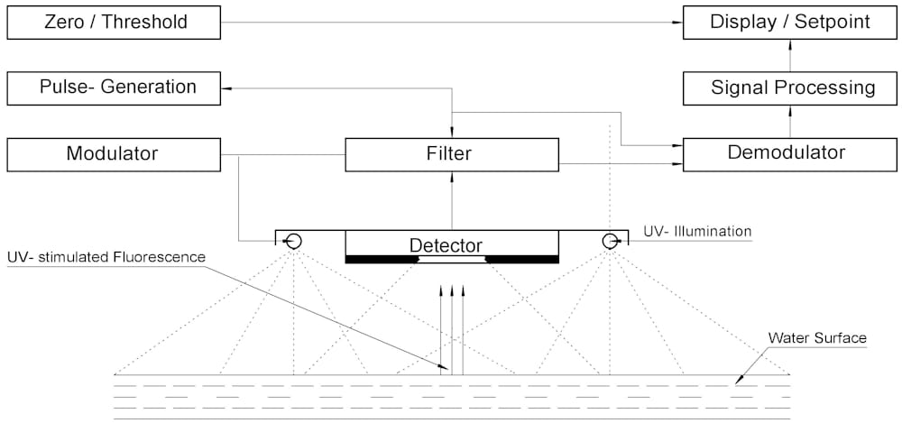
A sensor for contactless oil detection with a suitable UV radiation source is positioned above the water surface for fluorescence measurement.
Observation with the human eye gives an indication of the possible sensitivity of this method. Even small amounts of oil lead to interference color patterns and fluorescence. The response sensitivity of the fluorescence method is approx. 10x better than that of the eye.
This method can also be affected by interference factors
However, a suitable device design largely minimizes the effect of these interferences on the results.
Energy (E1 = hv1), here in the form of ultraviolet radiation, is absorbed by an atom or molecule.
The electrons are excited to move to a higher energy state. When the excited electrons fall back to the ground state, the radiant energy (E2 = hv2) is released again, but not entirely at the same wavelength as during energy absorption; it is also emitted at a wavelength in the visible spectrum and as thermal radiation (E3).
E1 = E2 + E3
The emitted wavelength (fluorescence radiation) is substance-specific. Among other things, oil contains aromatic compounds. Since each type of oil has a different composition, the fluorescence spectrum of the various oils also differs, but generally lies between 350 and 500nm.
The device is designed for continuous use with low maintenance in industrial environments. Its design reduces the effects of external interference to a minimum.
UV lamps or, optionally, UV LED arrays are used as the UV source. The UV sources are arranged above the
detector optics and cover a detection area of approx. 30cm in diameter. This
design enables oil detection even on moving water surfaces. Waves of up to 3cm have
no influence on the response sensitivity of the system.
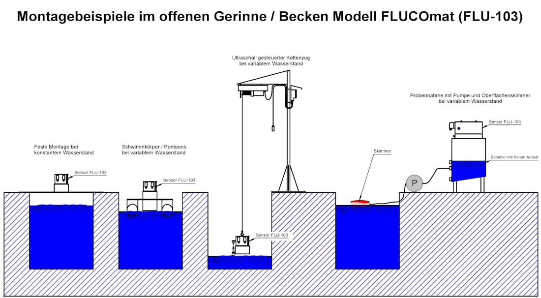
The receiver optics for detecting fluorescence are optimized for a distance of approx. 400mm between the water surface and the sensor. Changes in the distance between sensor and water surface of more than 75mm must be compensated for by a suitable installation (e.g. installation on pontoons, an ultrasonically controlled lift system, bypass containers, etc.).
Correct operation of the system is ensured by permanent monitoring of the following parameters:
Fault messages are indicated by four LEDs. A common relay reports a failure or malfunction to the control room. The results are transmitted via the analog output.
The model FLUCOmat (FLU-103) is used, among other things, to monitor:
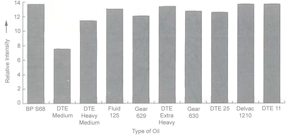
Figure 2 shows the sensitivity for several oils detected using a laboratory setup.
The following wastewater streams are mainly found in a power plant:
The water may be contaminated by lubricating oil, heat exchanger oil, turbine oil, etc. and is treated in the wastewater treatment plant (Figure 6).
Here, the model FLUCOmat (FLU-103) is used for reliable oil monitoring of the outlet
Benefit from more than 40 years of experience, field-proven measurement technology and personal advice. Together, we will find the right solution for your application. Visit our contact page and tell us about your project for a non-binding quote.
You need to load content from reCAPTCHA to submit the form. Please note that doing so will share data with third-party providers.
More InformationYou need to load content from Turnstile to submit the form. Please note that doing so will share data with third-party providers.
More InformationYou are currently viewing a placeholder content from Vimeo. To access the actual content, click the button below. Please note that doing so will share data with third-party providers.
More InformationYou are currently viewing a placeholder content from YouTube. To access the actual content, click the button below. Please note that doing so will share data with third-party providers.
More InformationYou need to load content from reCAPTCHA to submit the form. Please note that doing so will share data with third-party providers.
More Information